I was involved in the design of the recent Dynaco CDV-Pro CD Player. Being the top of the line CD player for the "new" Dynaco, this would have excellent audio quality and use the Pacific Microsonics HDCD decoder chip. How this CD player turned out became an object lesson to me on why it is so difficult to get sonically good consumer gear to the market. There is a story behind how the CDV-Pro did not come out as I had designed it. This site will give documentation on the final CDV-Pro, as shipped, and modification to it to bring it back to the quality level of the engineering prototypes.
- John Atwood
The schematics of the stock CDV-Pro given here were traced from a stock unit, and entered into the Protel schematic system - which would allow me to make PC boards of modifications, if needed. The files here are Acrobat .pdf files that were "printed" from the Protel schematics.
Only the D/A "mezzanine" board and the analog parts
of the main board were transcribed. These are the areas where
modifications are necessary.
Note: There was an error in both the stock
and modified D/A Converter board schematics involving RK51, 52,
53, 54. If you downloaded these schematics earlier, throw them
away and download the new ones (marked updated, and dated Oct.
22, 2000).
6/4/2001: The modification instructions have been updated to reflect the corrections above.
![]() CDV-Pro D/A Converter Board (PDF: 51Kbytes)
CDV-Pro D/A Converter Board (PDF: 51Kbytes)
![]() CDV-Pro Tube Line Amp (PDF: 48Kbytes)
CDV-Pro Tube Line Amp (PDF: 48Kbytes)
![]() CDV-Pro Power Supply (PDF: 64Kbytes)
CDV-Pro Power Supply (PDF: 64Kbytes)
If parts of the design look a little strange, especial the parts using "composite transistors", I didn't design those! If anyone finds what they think are errors in the schematic transcription, please e-mail me.
The first prototypes were put together by Arn Roatcap and myself, using the chassis and mechanism from a Proton-built CDV-1. As far as I know, there are only two prototypes in existence - I have one, and the other is in the New York area. My prototype was auditioned quite a bit in the San Francisco Bay Area, and nearly everyone who listened to it found it exceptional. A typical analogy was that it was to a regular CD player what a good LP was to CD (as far as natural sound goes). However, when the first production units were shipped, I started hearing complaints about the sound. As explained elsewhere, it turns out the audio chain was significantly changed - it measured better, but sounded much worse. This section will explain how to bring the stock design fairly close to the prototype design.
Warning: You should only attempt these modifications if you can: Carefully follow directions, skillfully and nondestructively remove parts from a PC board, and are careful to avoid static discharge (ESD). I cannot help out people who have problems with their modifications! Be aware that any modifications will void the manufacturer's warrantee - so if you have a new unit, let it break in for a while, to insure there are no "infant mortalities".
Schematics of updated CDV-Pro:
![]() Updated CDV-Pro D/A Converter "mezzanine" Board (PDF: 41Kbytes)
Updated CDV-Pro D/A Converter "mezzanine" Board (PDF: 41Kbytes)
View of the unmodified mezzanine board: 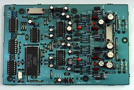
The parts removed from the mezzanine board: 
View of the updated mezzanine board (top side): 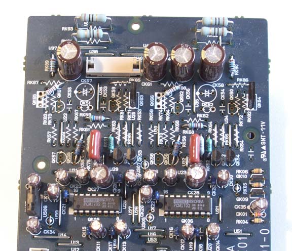
![]() Updated CDV-Pro Tube Line Amp (PDF:
43Kbytes)
Updated CDV-Pro Tube Line Amp (PDF:
43Kbytes)
The rather small regulator heatsinks can run quite hot. In particular, the 12 volt regulators (Q801 and Q804) run too hot, especially when playing a CD. Some of the heat can be removed from these regulators by shunting a power resistor from input to output. For the tube filament regulator (Q801), the value isn't too critical, and it was found that a 15 ohm, 5 watt resistor worked well. For the CD mechanism regulator(Q804), the value is a bit more critical, since the current draw varies a lot. It was found that a 50 ohm 3 watt resistor worked well. If your line voltage is high, check the output with a voltmeter. If it rises over 12.5 volts while idle, increase the resistor value. R801, a 10 ohm resistor in series with the filament supply rectifiers, is too high in value, and is prone to open-circuiting. Replace it with a 1.5 ohm 3 watt resistor. The cathodes of the 6922 run hot, since this is an RF tube designed for maximum transconductance at high plate current. Longer life and better linearity can be acheived by running the cathodes a little cooler. This can easily be done by replacing D805 with a jumper, or, more easily, soldering a wire across it. This lowers the per-tube heater voltage from 6.3 to 6.0 volts.
Step-by-step instructions for doing the modifications are here.
A question came up on what the B+ voltage is. It is about 205V at the output of the regulator, but will vary, depending on line voltage.
Several other people have worked on the CDV-Pro to improve its sound. Here are summaries of what they have done. If you would like to add your own modifications, e-mail me.
1. Better power supply filtering on the mezzanine board (suggested by John Broskie, tried out by Rich Curtis) - the 10 ohm/220uF filtering to the analog circuits is not very effective, and has a time constant right in the middle of the audio band. Replacing the 10 ohm resistors with low-resistance RF chokes still keeps high-frequency noise out, but preserves good regulation in the audio band. The audible effect is subtle, but there is an improvement in smoothness and clarity.